
Optimising the Server
If you've come this far, you've got a GNSS-backed Stratum 1 NTP server with excellent capability for experimentation, and the optimisation can begin!
One of the downsides of experimenting with NTP server optimisation is how long it takes for everything to settle after each change. It will generally take hours before you can see if your change has made a difference.
Hopefully this page can help save you some of your own time by letting you know which modification helped for me, and which didn't.
Page Index
| Category | Test Name | Improvement Observed |
|---|---|---|
| Pi | Stabilising the temperature | Yes |
| Pi | Finding Zero TC | Yes |
| Pi | Using a high-speed Micro SD Card | Yes |
| Pi | Returning to ntpheat | Yes |
| Pi | Setting a Fixed Clock Speed | No |
| Pi | Disabling Kernel Power Saving | Marginal |
| Pi | Disabling WiFi | Yes |
| Pi | Changing the Power Supply | No |
| GNSS | Setting the Cable Delay | Marginal |
| GNSS | Setting the power mode | No |
| GNSS | Setting a fixed location | No |
| GNSS | Antenna Selection | Marginal |
| Pi | Further Insulation Improvements | Yes |
| GNSS | Disabling SBAS | No |
| GNSS | Selecting GNSS constellations | In Progress |
| GNSS | Setting the PPS frequency | |
| Chrony | Setting the GNSS Offset | |
| Chrony | Changing to SOCK interface | |
| Chrony | Making Chrony stay in memory | |
| Chrony | Reducing 'niceness' | |
| Chrony | Using rtcsync | |
| Chrony | Adding Rate Limiting |
Pi - Stabilising the temperature
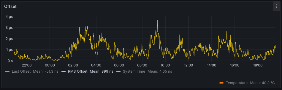
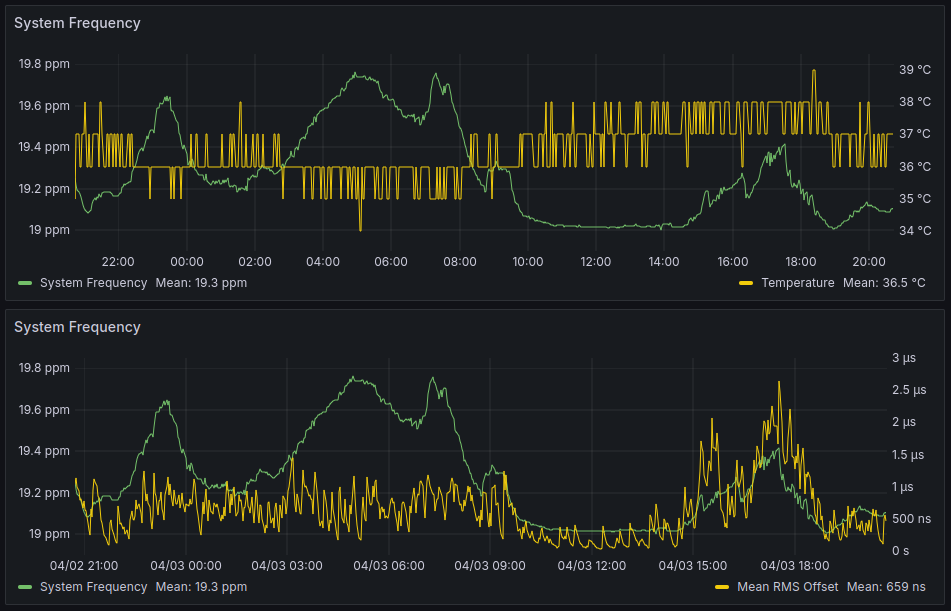
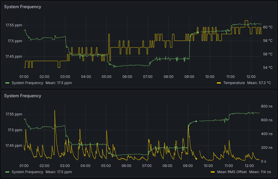
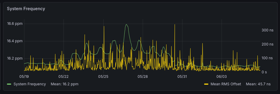
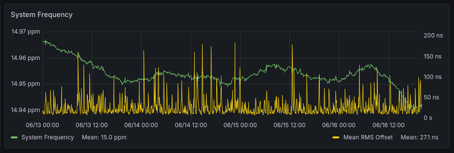
Let's consider the performance of the server during a normal (almost) 24h period. The mean RMS offset over the day is a little under 1 µs, with spikes up to almost 4 µs.
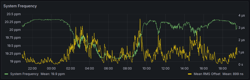
Where does this come from? The answer becomes clear when we overlay the system frequency. Chrony is good at correcting for slow system drifts, but when the system frequency changes sharply the disturbance is passed along.
And why does the system frequency change? Let's now overlay the CPU temperature on the frequency. The system clock is generated by a crystal oscillator on the Raspberry Pi board, and these are sensitive to fluctuations in temperature. There are many ways that oscillator designers improve stability across temperature, but these come at a cost. Since this is a cheap single-board computer and not a piece of metrology equipment, low cost parts are used!
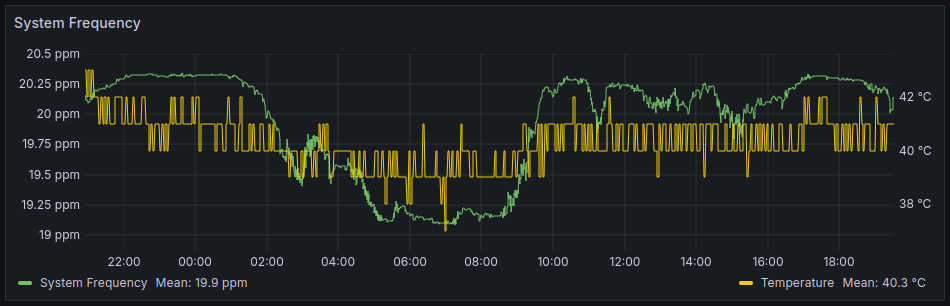
So if we want to improve the performance of our time server, we should start by looking at temperature.
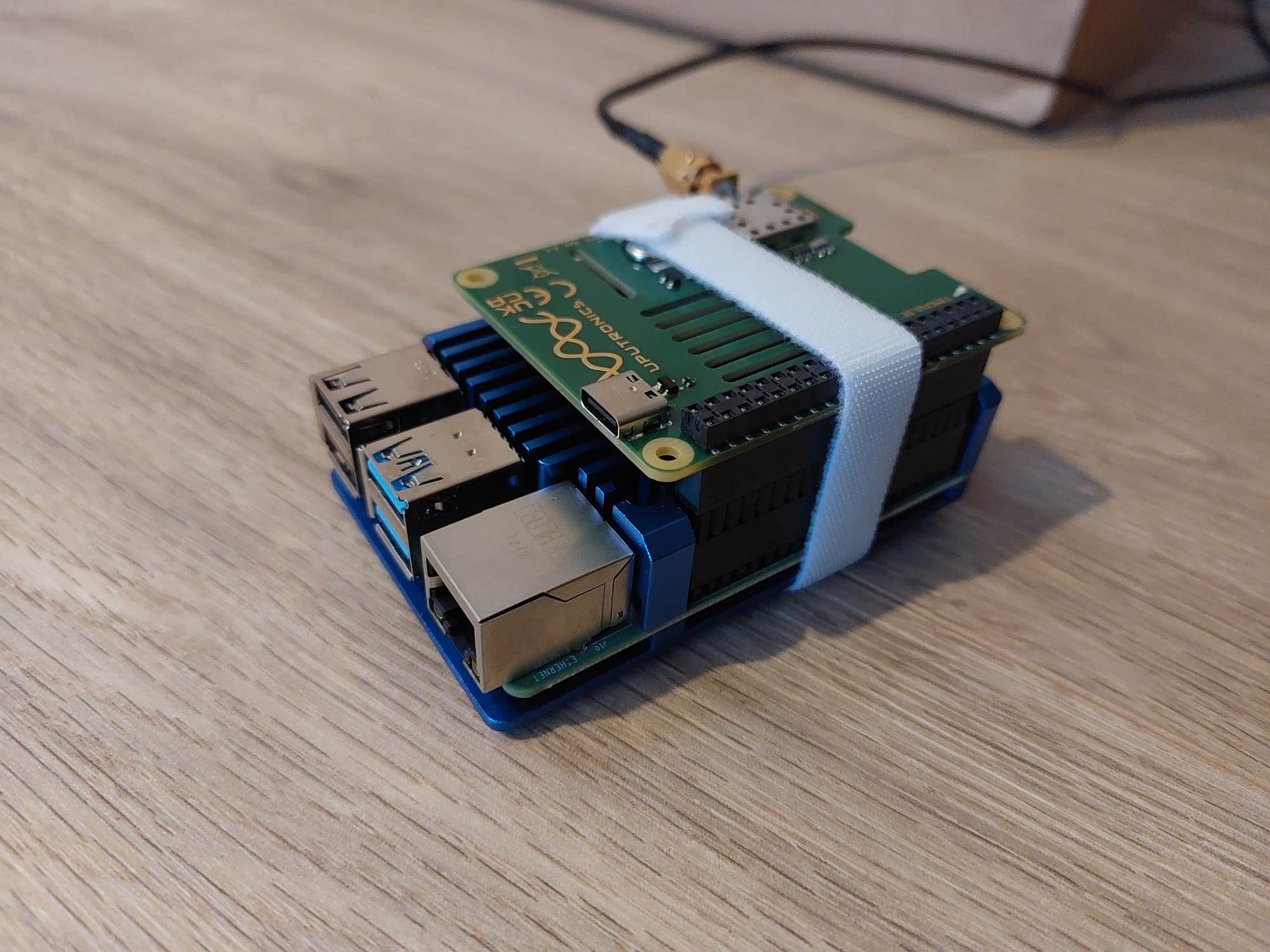
Adding thermal mass
To slow down temperature changes (and hopefully therefore eliminate the sharp system frequency changes), I added a large metal heatsink to the Raspberry Pi. The heatsink doesn't directly contact the oscillator, but it's still going to provide a fairly large and stable thermal mass around it.
After 24 hours, the performance was as below. The system frequency is definitely showing fewer sharp spikes, and this in turn has improved the Mean RMS Offset. It's an reduction of a little over 25%, which isn't bad for just adding a big heatsink!
Adding insulation
Given the relationship between temperature stability and RMS Offset seen in the previous test, the Raspberry Pi was placed inside a small cardboard box with some bubble wrap. Not enough for it to overheat, but enough to give it a fairly stable air mass.

A day later, and the system performance was as shown in the image below. The temperature is more stable (though it's not so obvious given the 1 °C resolution of the sensor), and this has greatly smoothed the system frequency.
RMS offset has fallen significantly as a result - down to 227 ns, which is a reduction of over 65%.

Insulation clearly has a very significant effect. If your Pi isn't insulated against room temperature changes already, this is a great idea.
The temperature was still swinging around a bit as the room temperature changed over the course of the day, though. This brought me onto the ntpheat script, linked below.
Active temperature stabilisation
The program 'ntpheat' reduces CPU temperature variations by running calculations if the CPU temperature is below a certain setpoint, and stopping the calculations if above the setpoint. What an elegant solution!

The only change I had to make to the script linked above was to change the line:
m.update("Nobody inspects the spammish repetition") So that it read:
m.update(b'Nobody inspects the spammish repetition')
Move the script to /usr/bin/
sudo mv /home/pi/ntpheat.sh /usr/bin/
And make it executable
sudo chmod +x /usr/bin/ntpheat.sh
Now we make a service:
sudo nano /etc/systemd/system/ntpheat.service
And paste in the following text.
Note, the -c modifier tells ntpheat how many times it should run. Running only once may not produce enough heat. The -t modifier tells it what setpoint to target.
[Unit]
Description=ntpheat

[Service]
ExecStart=python /usr/bin/ntpheat.sh -c 4 -t 50
Restart=on-failure

[Install]
WantedBy=multi-user.target
Now we enable the service, start it, and test to see that it's running.
sudo systemctl enable ntpheat.service
sudo systemctl start ntpheat.service
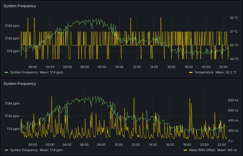
sudo systemctl status ntpheat.serviceThe image below shows how the system is performing after another 24 h period. The temperature is now very stable, as is the system frequency. It may not look like a huge change in system frequency stability, but look again at the Y axis - the variation is an order of magnitude less!
The mean RMS has dropped accordingly as a result of the better temperature stability. The 193 ns seen below is a reduction of another 15%.
Pi - Finding Zero TC
It's clear that temperature stability greatly helps the performance. We can never get perfect temperature stability, but we can move the setpoint to a temperature at which the crystal oscillator reacts less to temperature changes. This is the zero temperature coefficient (zero TC) point.
You can get a little more information and explanation about finding the zero TC point here:
Let's edit the ntpheat service:
sudo nano /etc/systemd/system/ntpheat.serviceEdit the line below:
ExecStart=python /usr/bin/ntpheat.sh -c 4 -t 50
The goal here is to sweep a range of temperatures until you find the point where the frequency offset reaches a min or max.
Once you set a temperature, save and close, then reload the daemon and restart ntpheat:
sudo systemctl daemon-reload
sudo systemctl restart ntpheat.service
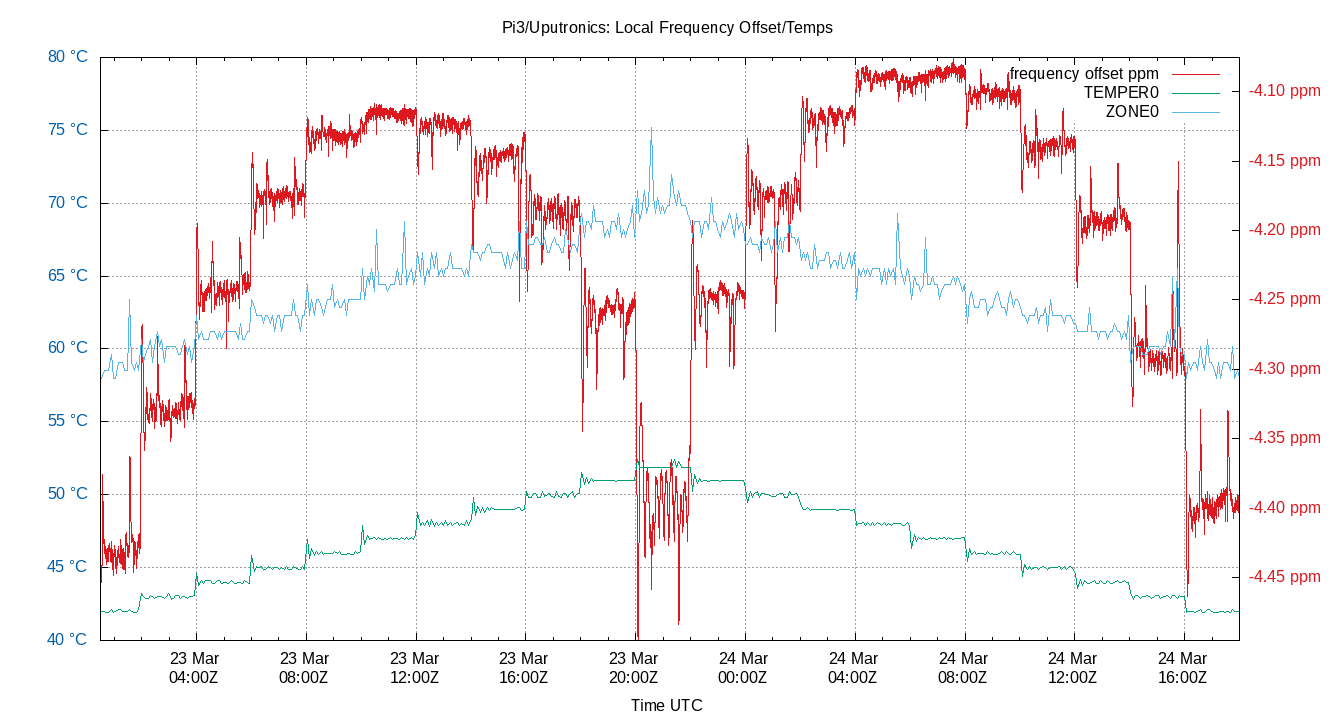
I did a rough sweep with 5 degree steps to find the approximate location of zero TC. You can see from the data below that the minimum occurs somewhere around 60 °C.
At this point, I decided to switch to 1 °C steps, but I didn't want to have to keep editing the ntpheat service over and over. Instead, I modified the ntpheat script (code below) and saved it as ntpheatsweep.sh
What this revised code does is to start warming to 5 °C below the requested point, then step up by 1 °C every two hours. Once it's stepped up ten times (so it's now 5 °C above the requested point), it starts to step back down. And so it repeats.
To use it, you pass the approximate temperature where you think zero TC is, and leave it to sweep back and forth.
#!/usr/bin/env python
#
# generate some heat!
#
# Wrap your RasPi in bubble wrap.  Then run ntpheat in the background.
# It will try to stabilize the CPU temperature at 65C by default.

# Sometimes one copy of ntpheat can use 100% of one CPU and
# still not heat up your RasPi as much as you want.  The temptation
# is to add more insulation to your RasPi, but then it will overshoot
# your target temperature if your load factor goes high.
#
# The solution is to run more than one copy of ntpheat.  This is
# easy to do with the -c option.
#
# To run 3 copies of ntpheat: ntpheat -c 3

import argparse
import hashlib
import os
import sys
import time

# Work with argvars
parser = argparse.ArgumentParser(description="make heat")
parser.add_argument('-c', '--copies',
                    default=[1],
                    dest='copies',
                    help="Number of copies to run.  Default is 1",
                    nargs=1,
                    type=int)
parser.add_argument('-t', '--temp',
                    default=[65.0],
                    dest='target_temp',
                    help="Temperature to hold.  Default is 65.0",
                    nargs=1,
                    type=float)
parser.add_argument('-w', '--wait',
                    default=[0.001],
                    dest='wait',
                    help="Set delay time in seconds, default is 0.1",
                    nargs=1,
                    type=float)
args = parser.parse_args()

args.copies[0] -= 1
while args.copies[0]:
    args.copies[0] -= 1
    pid = os.fork()
    if pid:
        # I am the fork
        break

zone0 = '/sys/class/thermal/thermal_zone0/temp'
cnt = 0

m = hashlib.md5()
temp = 0
max_cnt = args.wait[0] * 200000
# on a RasPi 3 the temp steps seem to be about 0.537 to 0.539C
temp_gate = args.target_temp[0]
starttime = time.time()

temp_setpoint = temp_gate - 5
step_no = 1
rising = True

while True:
    # on a RasPi 3, 200,000 of the m.update() can be one second
    delta = temp_setpoint - temp

    if 0 < delta:
        # heat it up
        m.update(b'Nobody inspects the spammish repetition')
    else:
        cnt = max_cnt
        # cools off slower than it heats up.
        # undocumented Python 'feature', no sleep less than 1 milli Sec
        sleep = args.wait[0] * 10.0 * -delta
        if 0.001 > sleep:
            sleep = 0.001
        time.sleep(sleep)

    cnt += 1
    # read the temperature every max_cnt
    if max_cnt < cnt:
        cnt = 0

        zone_data = open(zone0, 'r')
        for line in zone_data:
            temp = float(line) / 1000

        zone_data.close()

        currenttime = time.time()
        deltatime = currenttime - starttime

        if deltatime > 7200:

            if rising == True:
                temp_setpoint += 1
                step_no += 1
                # print(temp_setpoint)
            else:
                temp_setpoint -= 1
                step_no += 1
                # print(temp_setpoint)

            if step_no > 10:
                rising = not rising
                step_no = 1

            starttime = time.time()
I wanted this to run in the background just as ntpheat was, so I moved the new script to /usr/bin/ , made it executable, and edited the ntpheat service
sudo mv /home/pi/ntpheatsweep.sh /usr/bin/
sudo chmod +x /usr/bin/ntpheatsweep.sh
sudo nano /etc/systemd/system/ntpheat.service
The ntpheat service was modified to comment out the path to ntpheat.sh, and add one to ntpheatsweep.sh :
[Unit]
Description=ntpheat

[Service]
#ExecStart=python /usr/bin/ntpheat.sh -c 4 -t 50
ExecStart=python /usr/bin/ntpheatsweep.sh -c 4 -t 60
Restart=on-failure

[Install]
WantedBy=multi-user.target
Now the daemon is reloaded, and the ntpheat service restarted
sudo systemctl daemon-reload
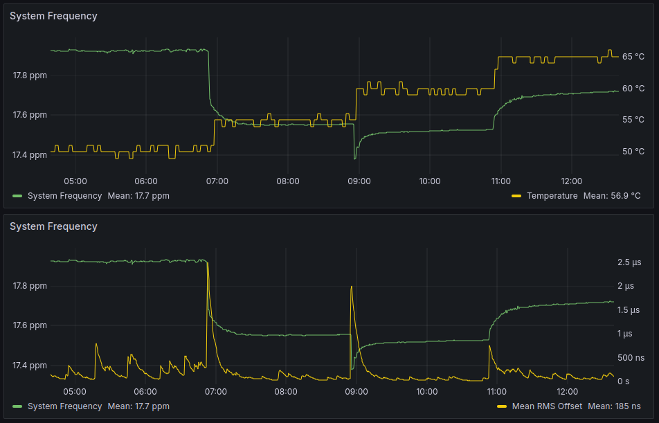
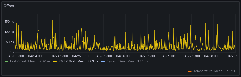
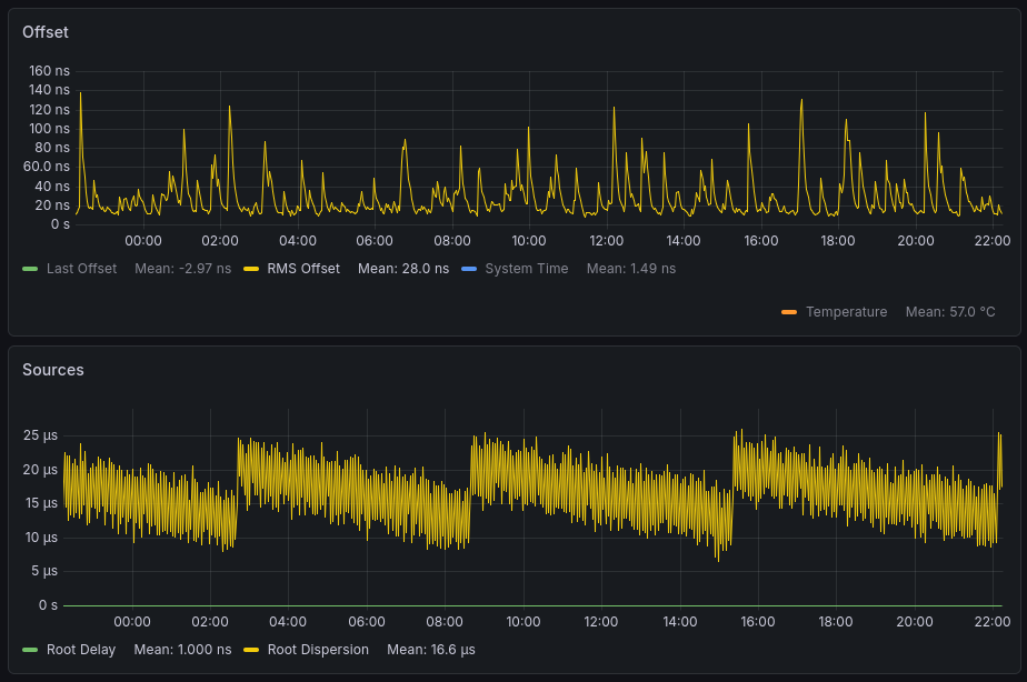
sudo systemctl restart ntpheat.serviceUltimately, the script didn't have to complete a full sweep - as shown in the image below, the zero TC turned out to be at 57 °C. If we then set ntpheat to this temperature, we'll minimise the effect of small temperature changes on the Pi's oscillator.
Note how the RMS offset spikes get smaller and smaller as we get closer to zero TC. This shows the very effect we're after!
The next step is to switch back to using ntpheat and setting it to our zero TC temperature.
sudo nano /etc/systemd/system/ntpheat.serviceThe ntpheat service was modified to comment out the path to ntpheatsweep.sh, and uncomment the one to ntpheat.sh. The setpoint was also changed to 57 °C.
[Unit]
Description=ntpheat

[Service]
ExecStart=python /usr/bin/ntpheat.sh -c 4 -t 57
#ExecStart=python /usr/bin/ntpheatsweep.sh -c 4 -t 60
Restart=on-failure

[Install]
WantedBy=multi-user.target
Now the daemon is reloaded, and the ntpheat service restarted
sudo systemctl daemon-reload
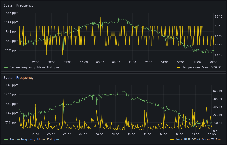
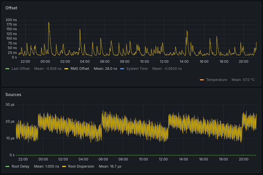
sudo systemctl restart ntpheat.serviceFollowing 24 hours of operation at zero TC, the performance is as shown below. We see another good reduction in mean RMS offset. This now sits at 74 ns - a reduction of a further 62%!
Pi - Using a high-speed Micro SD Card
Does the Raspberry Pi's disk read/write performance affect timekeeping? It seems like a reasonable assumption - perhaps a higher maximum disk speed allows the system to operate away from any IO bottlenecks which may impact the periodicity. Alternatively, maybe a standard Micro SD card is already far from being a bottleneck.
Consider the table below (Source: Wikipedia), differentiating all the various speed classes of Micro SD cards can be a complex business. Class 10 can mean all manner of different write speeds!

The NTP server setup described so far has been created and operated on the left Micro SD card below. This is a generic low-cost Class 10 card. It could have a write speed of anywhere between 10 MB/s and 90 MB/s (but is probably at the low end).
The disk on the right is a new Micro SD card from Sandisk, which has more specific markings. Looking at the V30 class, we know this operates at 30 MB/s. Additionally, this has the newer Application Performance Class specified. This card is an A2 (the highest Application Performance Class), which means it can operate at 4,000 reading and 2,000 writing operations per second. This is a useful consideration for a card that applications (such as an operating system) will run on. (It was also under €10 - amazing what you can get for such a low price)

To perform this test, I used the Ubuntu 'Disks' application to make an image of the original Micro SD card, and wrote the image to the new Micro SD card. I then swapped the two cards over (so the Pi was running on the new one) and left it for 24 hours to tick along.
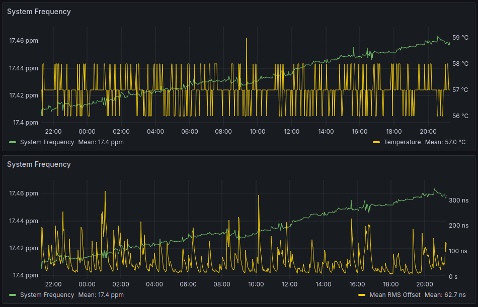
After a day, the performance was as shown below. The change did indeed seem to have some impact - the new value of mean RMS offset of 62.7 ns is a reduction of 15%.
Pi - Returning to ntpheat
The previous experiment to find Zero TC got me wondering - is there an optimum number of copies of the script to run? (Recall that the number of copies is set using the -c modifier)
I used 4 copies in the previous tests, as in earlier experimentation I found that I needed more than one copy to reach a high enough temperature. That was as scientific as the process got. But perhaps there's a link between the number of copies an the stability, as they'll all be polling the temperature sensor and giving work to the CPU at slightly different times.
I modified the ntpheat script again, as below. The new script starts with one copy, and adds another every 24 hours until you stop it.
#!/usr/bin/env python
#
# generate some heat!
#
# Wrap your RasPi in bubble wrap.  Then run ntpheat in the background.
# It will try to stabilize the CPU temperature at 65C by default.

# Sometimes one copy of ntpheat can use 100% of one CPU and
# still not heat up your RasPi as much as you want.  The temptation
# is to add more insulation to your RasPi, but then it will overshoot
# your target temperature if your load factor goes high.
#
# The solution is to run more than one copy of ntpheat.  This is
# easy to do with the -c option.
#
# To run 3 copies of ntpheat: ntpheat -c 3

import argparse
import hashlib
import os
import sys
import time

# Work with argvars
parser = argparse.ArgumentParser(description="make heat")
parser.add_argument('-c', '--copies',
                    default=[1],
                    dest='copies',
                    help="Number of copies to run.  Default is 1",
                    nargs=1,
                    type=int)
parser.add_argument('-t', '--temp',
                    default=[65.0],
                    dest='target_temp',
                    help="Temperature to hold.  Default is 65.0",
                    nargs=1,
                    type=float)
parser.add_argument('-w', '--wait',
                    default=[0.001],
                    dest='wait',
                    help="Set delay time in seconds, default is 0.1",
                    nargs=1,
                    type=float)
args = parser.parse_args()


zone0 = '/sys/class/thermal/thermal_zone0/temp'
cnt = 0
fork = False

m = hashlib.md5()
temp = 0
max_cnt = args.wait[0] * 200000
# on a RasPi 3 the temp steps seem to be about 0.537 to 0.539C
temp_gate = args.target_temp[0]
starttime = time.time()


while True:
    # on a RasPi 3, 200,000 of the m.update() can be one second
    delta = temp_gate - temp

    if 0 < delta:
        # heat it up
        m.update(b'Nobody inspects the spammish repetition')
    else:
        cnt = max_cnt
        # cools off slower than it heats up.
        # undocumented Python 'feature', no sleep less than 1 milli Sec
        sleep = args.wait[0] * 10.0 * -delta
        if 0.001 > sleep:
            sleep = 0.001
        time.sleep(sleep)

    cnt += 1
    # read the temperature every max_cnt
    if max_cnt < cnt:
        cnt = 0

        zone_data = open(zone0, 'r')
        for line in zone_data:
            temp = float(line) / 1000

        zone_data.close()

        currenttime = time.time()
        deltatime = currenttime - starttime

        if deltatime > 86400:
            if fork == False:

            	pid = os.fork()
            	if pid:
                	# I am the fork
                	fork = True

            	starttime = time.time()
The test was kicked off on a Saturday afternoon and left for a week. At the end of the test, the data was as below:
| Ntpheat copies | Mean RMS Offset (ns) |
| 1 | 116 |
| 2 | 92.4 |
| 3 | 59.3 |
| 4 | 56.3 |
| 5 | 43.6 |
| 6 | 53.8 |
| 7 | 47.9 |
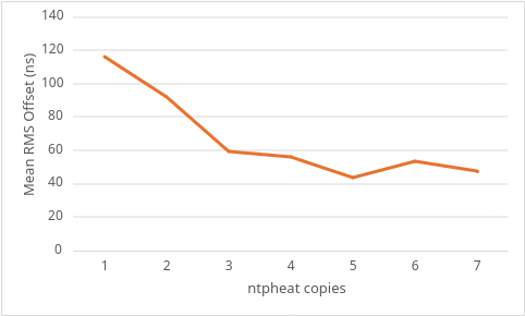
It's clear from the data that there is indeed an impact on stability resulting from the number of ntpheat copies that are run. There's going to be some error within the results, of course, so I don't think we can conclude that 5 copies will always be better than 4 copies. There may have been some environmental differences during that 24h period that I haven't found yet.
What I think we can conclude is that it makes sense to run 4 or more copies of ntpheat for improved stability.
Pi - Setting a Fixed Clock Speed
The clock speed of the Raspberry Pi adjusts depending on the system load. This allows it to save power when not doing very much, and to ramp up quickly as more demands are placed upon it. Perhaps these changes in core frequency affect timekeeping.
Open the config file:
sudo nano /boot/firmware/config.txtAdd the following lines (arm_boost=1 may already be present) to force the Pi to run always at maximum speed.
# Run as fast as firmware / board allows
arm_boost=1
force_turbo=1
Reboot the Pi:
sudo rebootMean RMS Offset (24h) before: 43.6 ns
Mean RMS Offset (24h) after: 45.9 ns
All in all, no improvement observed over 24h. The 2 ns degradation is most likely just statistical error.
Pi - Disabling Kernel Power Saving
Another method the Pi uses to save power when under low load is to use 'dynamic ticks'. This allows the system clock to skip cycles to save power. That doesn't sound ideal for a time server!
Open the config file:
sudo nano /boot/firmware/config.txtAdd the following lines:
# Disable kernel power saving / dynamic ticks
nohz=off
Reboot the Pi:
sudo rebootMean RMS Offset (24h) before: 43.6 ns
Mean RMS Offset (24h) after: 40.6 ns
A small improvement over 24 hours, I think. It's close to the statistical error, though.
Pi - Disabling WiFi
We're not using WiFi - maybe we should turn it off. It'll prevent some system processing, so perhaps performance of the time server will be affected.
Open the config file:
sudo nano /boot/firmware/config.txtAdd the following line:
dtoverlay=pi3-disable-wifiReboot the Pi:
sudo rebootMean RMS Offset (24h) before: 40.6 ns
Mean RMS Offset (24h) before: 32.9 ns
This improved performance more than I expected - a fairly clear 7.7 ns reduction in Mean RMS offset over 24 hours.
Pi - Changing the Power Supply
I started this test with the suspicion that the Raspberry Pi power supply may be responsible for some of the remaining disturbance in the system. My theory was that the official power supply, with its datasheet stating ±2% line regulation and ±5% load regulation was allowing the normal changes in the mains voltage to couple through into the Pi.
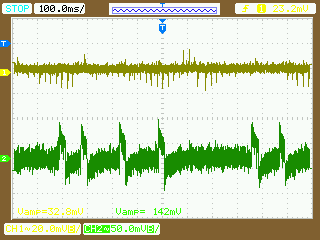
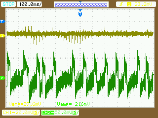
I started by monitoring the 5V and 3.3V rails of the Pi. The 5V rail comes from the power supply directly, and the 3.3V rail is regulated down from this for use by accessories (such as our GNSS receiver).
In the two images below, Channel 1 (yellow) is 3.3V and Channel 2 (green) is 5V. Both measurements are AC coupled, so we're just looking at the high frequency components. Spikes of almost 100mV can be seen on the 5V rail in the left image. These turned out to be from the ntpheat script running bursts of calculations to maintain the temperature - ntpheat was disabled and the 5V rail became much quieter (right image).


Of course we've seen that using ntpheat improves performance, so we can't just turn it off and expect the improved power supply rail stability to improve matters. Look again at the 3.3V rail (yellow), though - the spikes on the 5V rail aren't appearing on the 3.3V rail. That shows that the Power Supply Rejection Ratio of the linear regulator used on the Pi to generate the 3.3V rail is pretty good. It's able to reject the noise.
Just like the 3.3V rail for accessories, the microcontroller/CPU on the Pi board isn't getting its power directly from the USB port. The schematic shows that it's also coming from the same linear regulator (U2). So I think it's clear that we needn't worry too much about the noise from the USB power supply. As long as the power supply can handle the current requirements, it'll be fine.
To further explore this point, I powered the Pi from a battery and monitored the 5V and 3.3V rails again. Batteries are often used in real electronics R&D when we want to eliminate power supply noise from a circuit under test. The left image below from the test with the official PSU again, and the right one is the test with the battery. That's right, it's actually worse! The setup with the battery is less able to control the voltage when the current changes suddenly - this could be from something as simple as the thickness of the wire used to connect the Pi to the battery.
So in short, do you need to hunt for a quiet power supply to get maximum clock performance?
No.
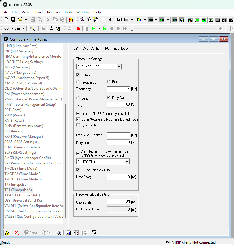
GNSS - Setting the Cable Delay
One important GNSS receiver setting is the cable delay. By telling the receiver how long the cable is, it'll give more precise PPS clock edges.
Because different coaxial cables have different delay characteristics, we need to do a quick calculation. Look at your cable and see what type it is (mine is RG174-U), then get a datasheet for that type. I found a datasheet on Mouser that states that RG174-U has a delay of 5.03 ns/m, and my cable is 5 m long. So my cable delay is 25 ns.
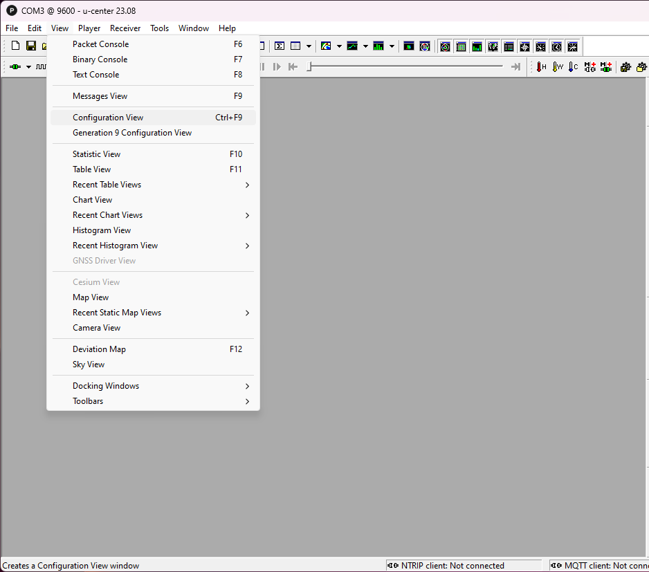
- Open up U-Center and connect the GNSS receiver.
- Enter 'Configuration View'
- Go to the TP5 section and enter your calculated delay into the 'Cable Delay' field
- Click on 'Send' at the bottom of the configuration window
- Go to the CFG section and select 'Save current configuration'
- Click on 'Send' at the bottom of the configuration window
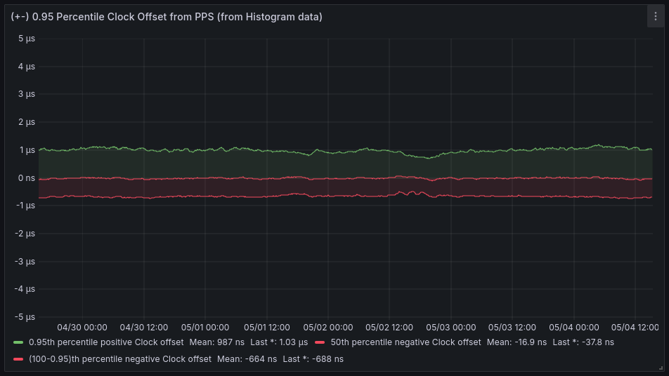
- Click on 'Cold Boot' in the top right of the main window
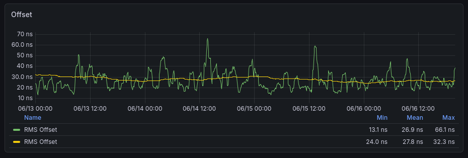
The results were pretty much as expected - the GPS data (green/red graphs below) showed a small improvement, with the offsets improving a little. The Chrony data (yellow graphs) showed very marginal changes (32.3 ns reducing to 29.2 ns).
It's a small improvement, but also very little effort to set up.
Before

After

GNSS - Setting the power mode
We know that the GNSS receiver is in its default configuration, as we reset it previously. Now the handy ubxtool command can be used to make changes.
The first thing to do is to check the version of your receiver.
ubxtool -p MON-VER ::/dev/ttyAMA0
In my case, I got the following response. Note the last line about protVer
UBX-MON-VER:
  swVersion ROM CORE 3.01 (107888)
  hwVersion 00080000
  extension FWVER=SPG 3.01
  extension PROTVER=18.00
  extension GPS;GLO;GAL;BDS
  extension SBAS;IMES;QZSS
WARNING:  protVer is 10.00, should be 18.00.  Hint: use option "-P 18.00"
Let's update the protVer and run the command again to see if the warning is gone.
export UBXOPTS="-P 18"
ubxtool -p MON-VER ::/dev/ttyAMA0
Looks like it's ready to go.
UBX-MON-VER:
  swVersion ROM CORE 3.01 (107888)
  hwVersion 00080000
  extension FWVER=SPG 3.01
  extension PROTVER=18.00
  extension GPS;GLO;GAL;BDS
  extension SBAS;IMES;QZSS
Now we check the power mode
ubxtool -p CFG-PMS ::/dev/ttyAMA0And in response we see:
UBX-CFG-PMS:
 version 0 powerSetupValue 1 period 0 onTime 0x0 reserved1 0 0
A powerSetupValue of 1 means that the receiver is in 'Balanced' mode. Let's change this to 0 to enter into 'Full Power' mode
ubxtool -p CFG-PMS,0 ::/dev/ttyAMA0A quick check that the setting change worked
ubxtool -p CFG-PMS ::/dev/ttyAMA0The response we get is:
UBX-CFG-PMS:
 version 0 powerSetupValue 0 period 0 onTime 0x0 reserved1 0 0
Looks good, now we save the configuration, and do a cold boot of the GNSS receiver, and wait to see if there's an impact.
ubxtool -p SAVE ::/dev/ttyAMA0
ubxtool -p COLDBOOT ::/dev/ttyAMA0
After 24 hours of operation, no particular impact was seen on the GPSD data. The Mean RMS Offset in Chrony was 28.6 ns, down from 29.2 ns. This is likely within the normal error over a 24h period.
I don't think this change has had any impact.
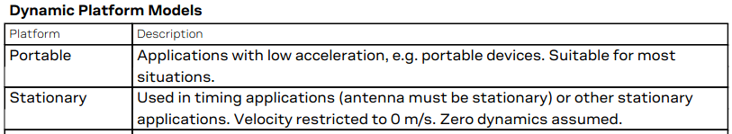
GNSS - Setting a fixed location
The u-blox GNSS receiver has twelve platform models available which adjust the navigation engine. According to the u-blox M8 Receiver Description, when correctly selected, these "improve the receiver's interpretation of the measurements and thus provide a more accurate position output".
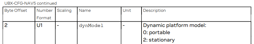
Let's see what's set by default
ubxtool -p CFG-NAV5 ::/dev/ttyAMA0The result is below:
UBX-CFG-NAV5:
 mask 0xffff dynModel 0 fixmode 3 fixedAlt 0 FixedAltVar 10000
 minElev 5 drLimit 0 pDop 250 tDop 250 pAcc 100 tAcc 350
 staticHoldThresh 0 dgpsTimeOut 60 cnoThreshNumSVs 0
 cnoThresh 0 res 0 staticHoldMaxDist 0 utcStandard 0
 reserved x0 0
dynModel is 0, which means 'Portable'. We can see from the u-blox M8 Receiver Description that 'Stationary' may be more suited to our use case.
Let's update the model:
ubxtool -p MODEL,2 ::/dev/ttyAMA0
And a sanity check that the setting worked
ubxtool -p CFG-NAV5 ::/dev/ttyAMA0The output is as follows:
UBX-CFG-NAV5:
 mask 0xffff dynModel 2 fixmode 3 fixedAlt 0 FixedAltVar 10000
 minElev 5 drLimit 0 pDop 250 tDop 250 pAcc 100 tAcc 350
 staticHoldThresh 0 dgpsTimeOut 60 cnoThreshNumSVs 0
 cnoThresh 0 res 0 staticHoldMaxDist 0 utcStandard 0
 reserved x0 0
Now we save the configuration, and do a cold boot of the GNSS receiver, and wait to see if there's an impact.
ubxtool -p SAVE ::/dev/ttyAMA0
ubxtool -p COLDBOOT ::/dev/ttyAMA0
After 24 hours of operation, no particular impact was seen on the GPSD data. The Mean RMS Offset in Chrony was 30.7 ns, up from 28.6 ns. This is likely within the normal error over a 24h period.
I don't think this change has had any impact, either.
GNSS - Antenna Selection
Professional GNSS users will opt for proper GNSS timing antennas. These look at a narrower cone of the sky to reduce the effect of multipath interference and any malicious interference from ground level.
But will a NAIS (now Panasonic) CCAH32ST01 Timing Antenna borrowed for a few days from work have any useful impact on our Raspberry Pi time server? How will it compare to a generic GNSS antenna (the type you sometimes get free with a receiver), and to a €50 uBlox ANN-MB Active Antenna?
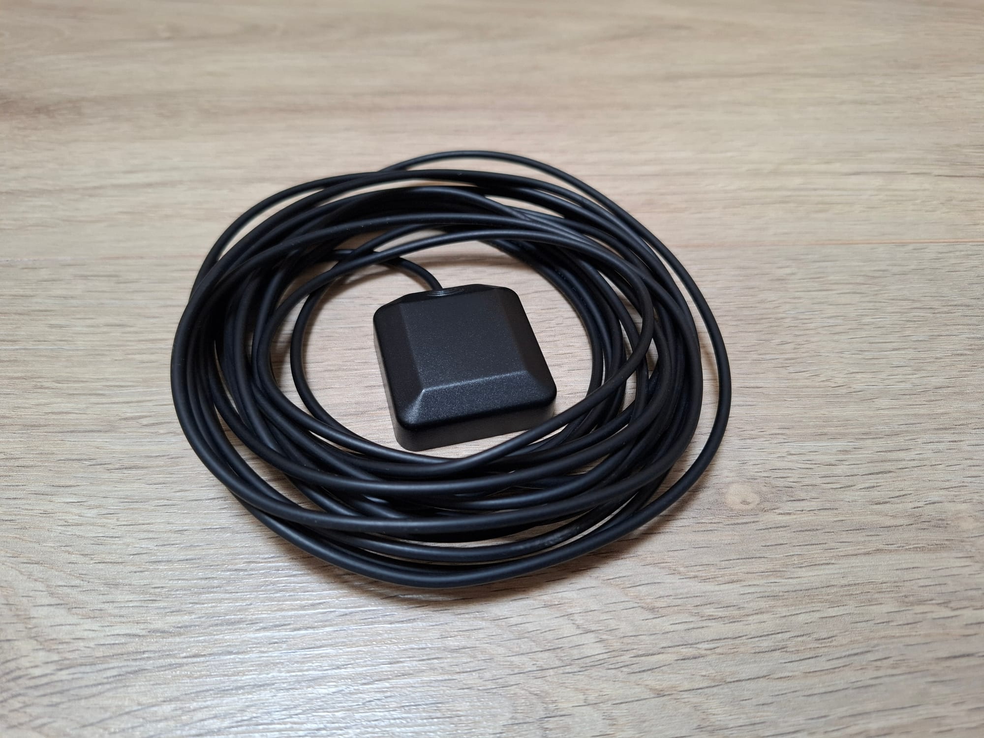


Left to Right: Generic GNSS Antenna, NAIS CCAH32ST01, uBlox ANN-MB
Each antenna was set up and left to run for a day. First the generic antenna, then the timing antenna, and finally the uBlox antenna. The latter two were mounted outside as they're weatherproof, and the generic antenna was placed under a skylight to give each the best sky view that was feasible.
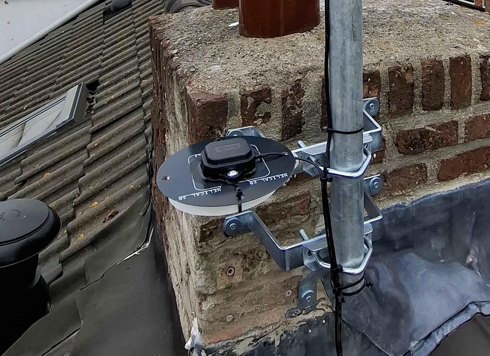
It's worth noting that the timing antenna specifies a slightly higher voltage requirement for its internal amplifier than the other two antennas. This has been tested with and without a dedicated power supply using a bias-tee, and it turns out that it runs just fine on the 3.3 V delivered by the uBlox GNSS receiver I'm using.
Onto the results, shown as one long three day run for easy comparison. The dotted blue line shows when the antenna was swapped. First was the generic antenna, then the timing antenna, and finally the uBlox antenna.
GNSS Performance:
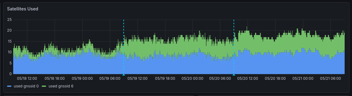
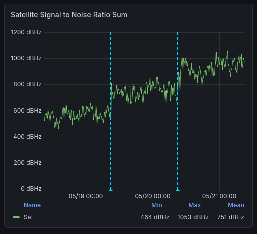
It's clear that the timing antenna has better performance than the generic antenna, but the uBlox antenna outperforms it by about an equal margin in this setup. Each manages to use more satellites than the last, and if we sum up the Signal to Noise ratio of each satellite used, we see a big jump each time. (Yes, summing the SNR and getting hundreds of dBHz is a dirty hack, but it gets the point across!)
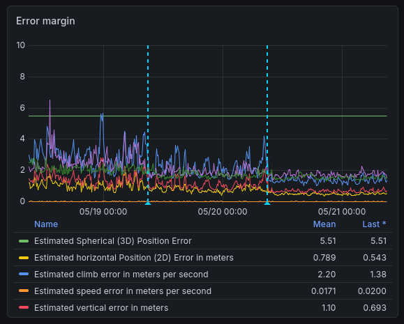
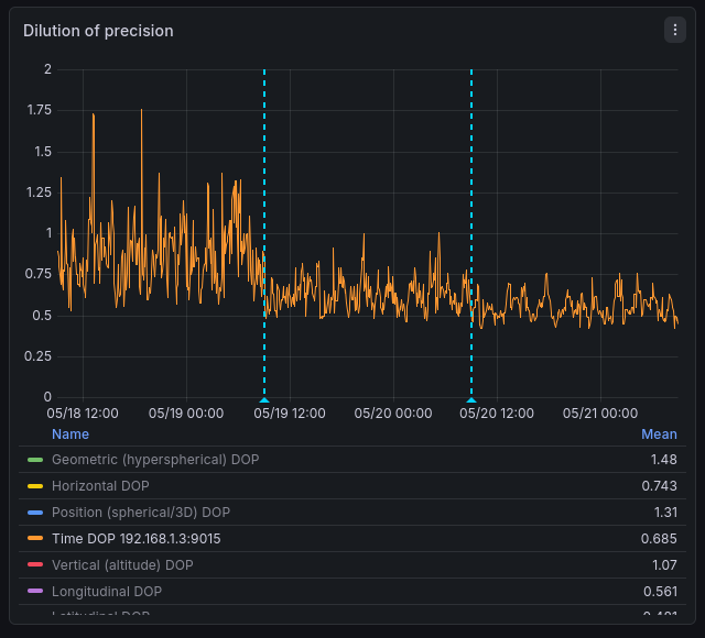
Onto the calculated error and the Time Dilution of Precision (TDOP) values, we can see that each antenna again outperforms the last. Error is reduced as we get better signal strength from more satellites.
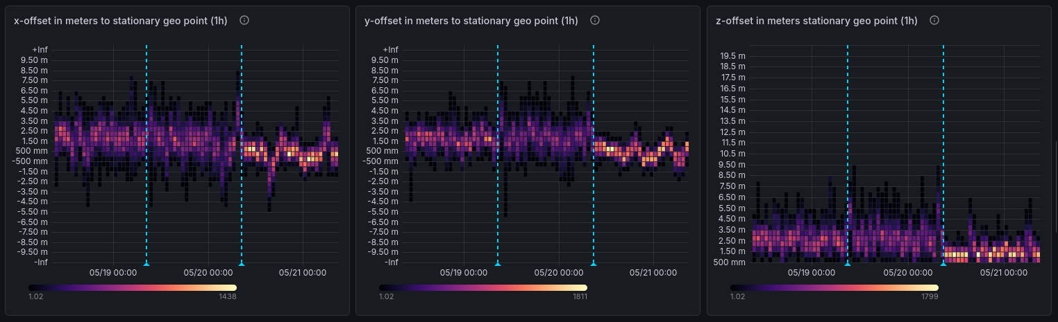
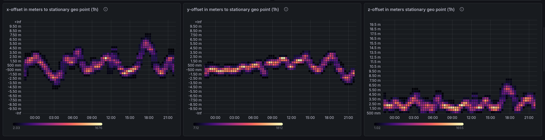
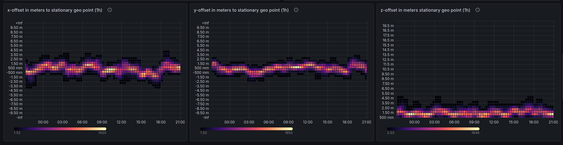
As a point of curiosity, though not something that impacts timing, we can also see that the uBlox antenna also improved the location precision. The heatmap above shows the offset between the reported location and a static point. It really tightens up with the uBlox antenna!
Timing Performance:
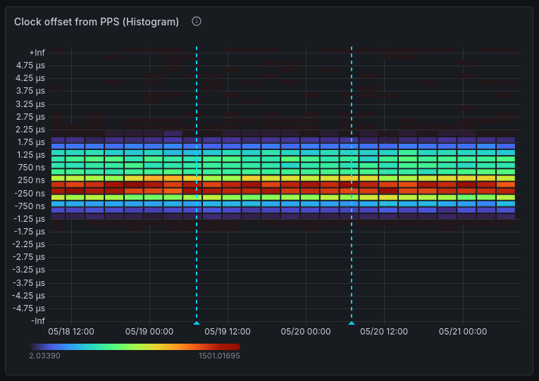
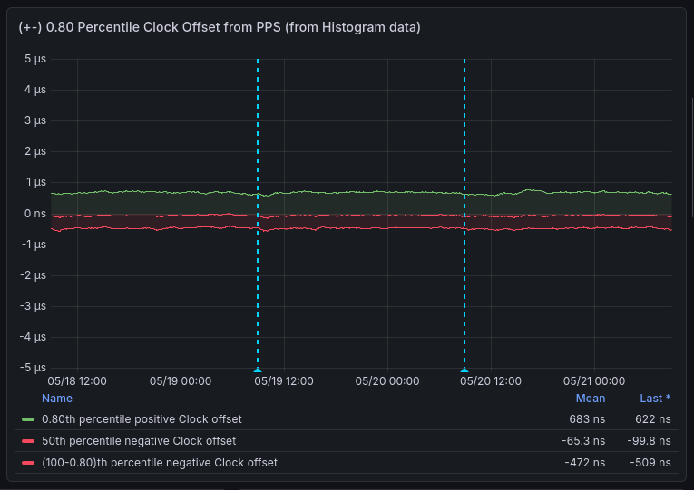
No antenna shows any particular improvement (or degradation) when it comes to the clock offset, even though the reported timing error was shown to reduce in the last images.
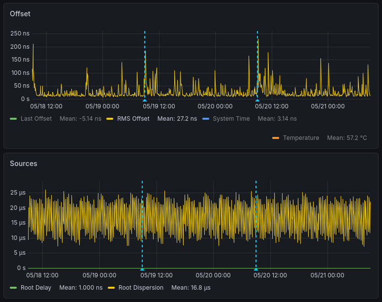
No particular difference is in observed in RMS Offset or Root Dispersion between the antennas over the three day period. The small spikes in RMS Offset around the late morning of May 20th are most likely temperature related (read on to the next topic to see how this has been resolved!). So the actual effect of antenna selection on timing seems to be negligible in this setup.
I've chosen to stick with the uBlox antenna, as it's performing very well from a signal strength and satellite acquisition perspective. It seems that the antenna choice just isn't the limiting factor in this setup.
So, to revisit the question, did a professional timing antenna have any useful impact on our Raspberry Pi time server?
No.
(Which is good, as it removes the temptation to buy one of my own)
Timing antennas have their uses, but the Raspberry Pi NTP server (or more likely the GNSS receiver used in it) just isn't at the point where this short of investment makes a difference.
Pi - Further Insulation Improvements
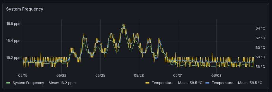
Following on from the first section on stabilising the temperature, I noticed when running the previous tests that the system frequency was consistently dropping around midday, which is when the room that the server is in gets warmest from the sun shining on the roof. This led me to think that the temperature stability wasn't yet properly under control, despite the improvements so far.
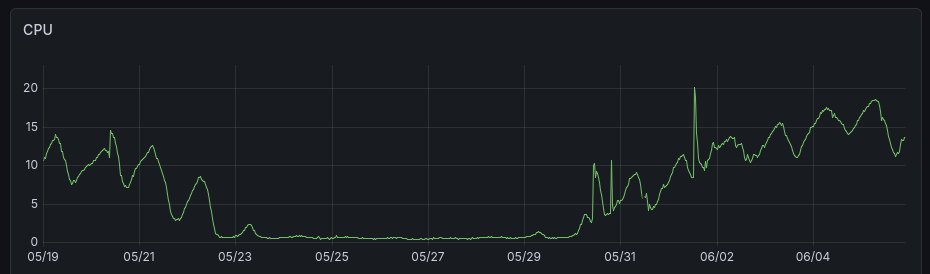
A few days of hot weather proved this, when the server CPU usage fell to near zero and the frequency became very variable.
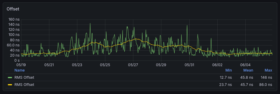
This in turn led to a big (relatively speaking) increase in the RMS Offset during the unstabilised period, shown below. The second image shows rolling averages of the RMS Offset to show the impact more clearly.
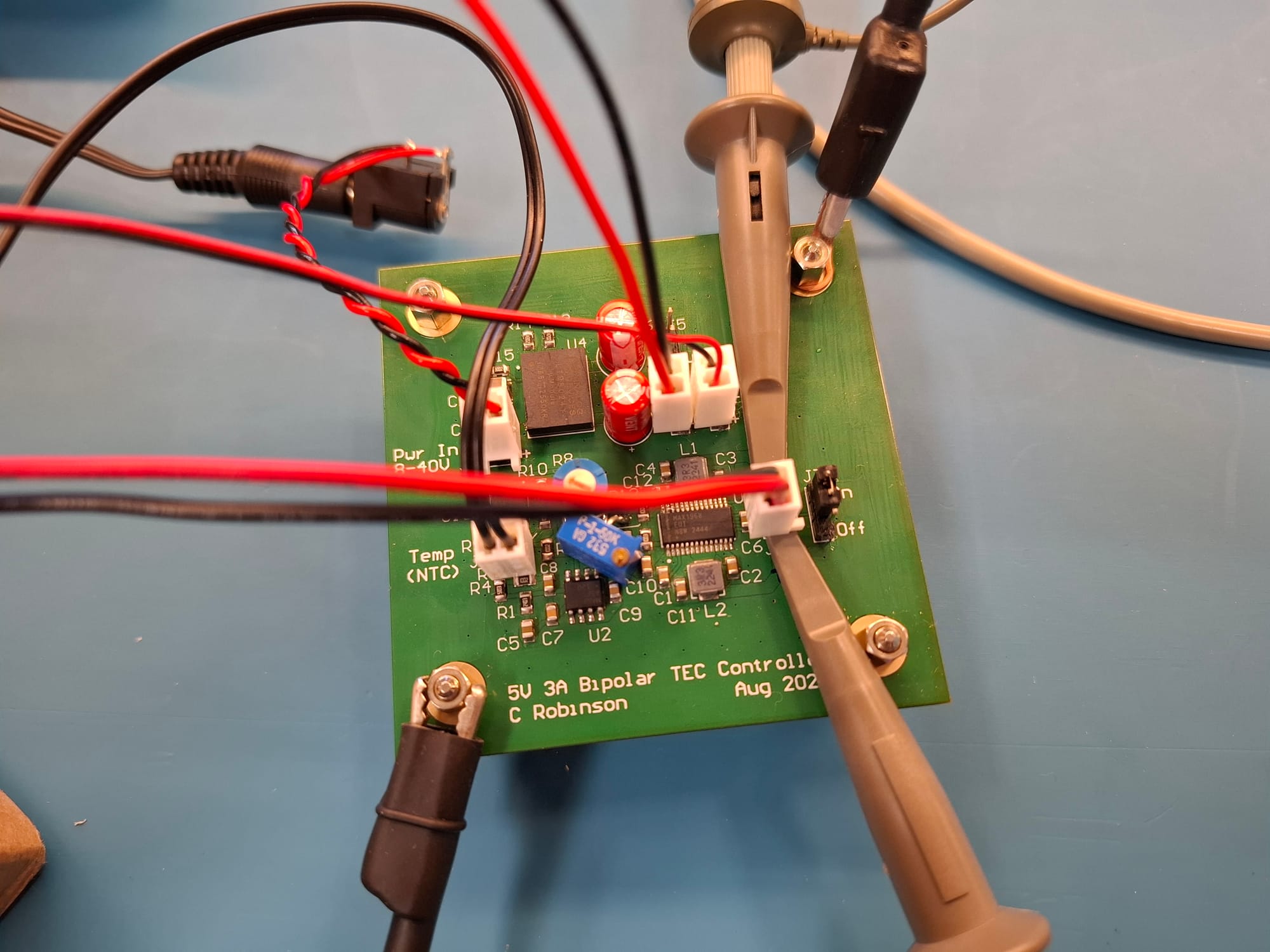
To address this, I created a temperature stabilised enclosure for the NTP server using a thermoelectric cooler (TEC). This is a simple circuit based on the MAX1968 from Analog Devices, which drives an Air-Air Thermoelectric Cooler from Farnell with fans on each side. This is used to control the temperature inside an expanded polystyrene box, into which the NTP server is placed.
The server is actually inside a bubble wrap envelope (not shown), and is on a spacer to prevent it from sitting directly on the bottom of the polystyrene box where there could be a shorter thermal path to the outside world. While the server was being moved, I also installed some thermal gap filler material between the Raspberry Pi crystal oscillators and the heatsink enclosure. This should reduce the impact of any air movement over them, and give better thermal stability.
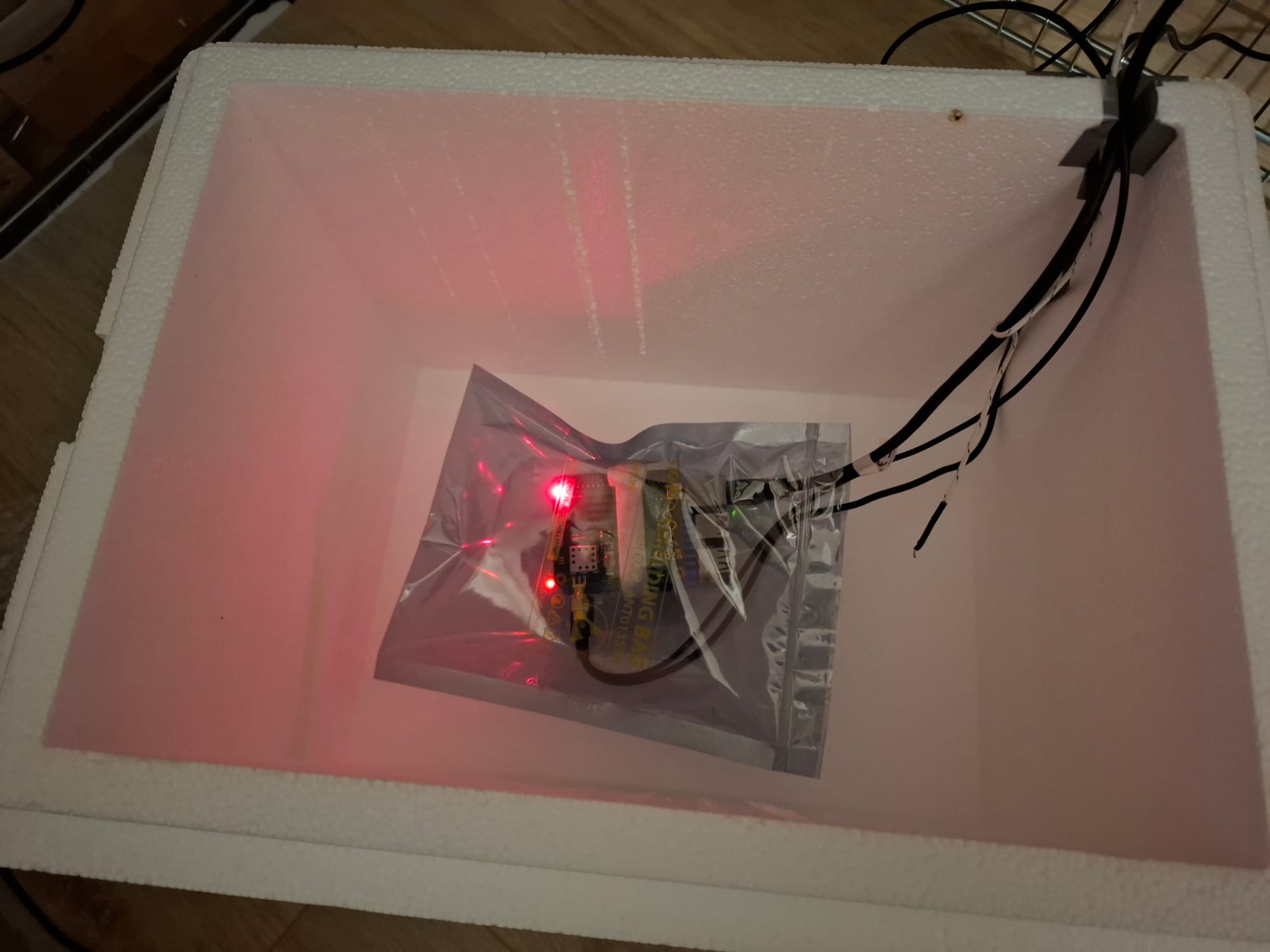
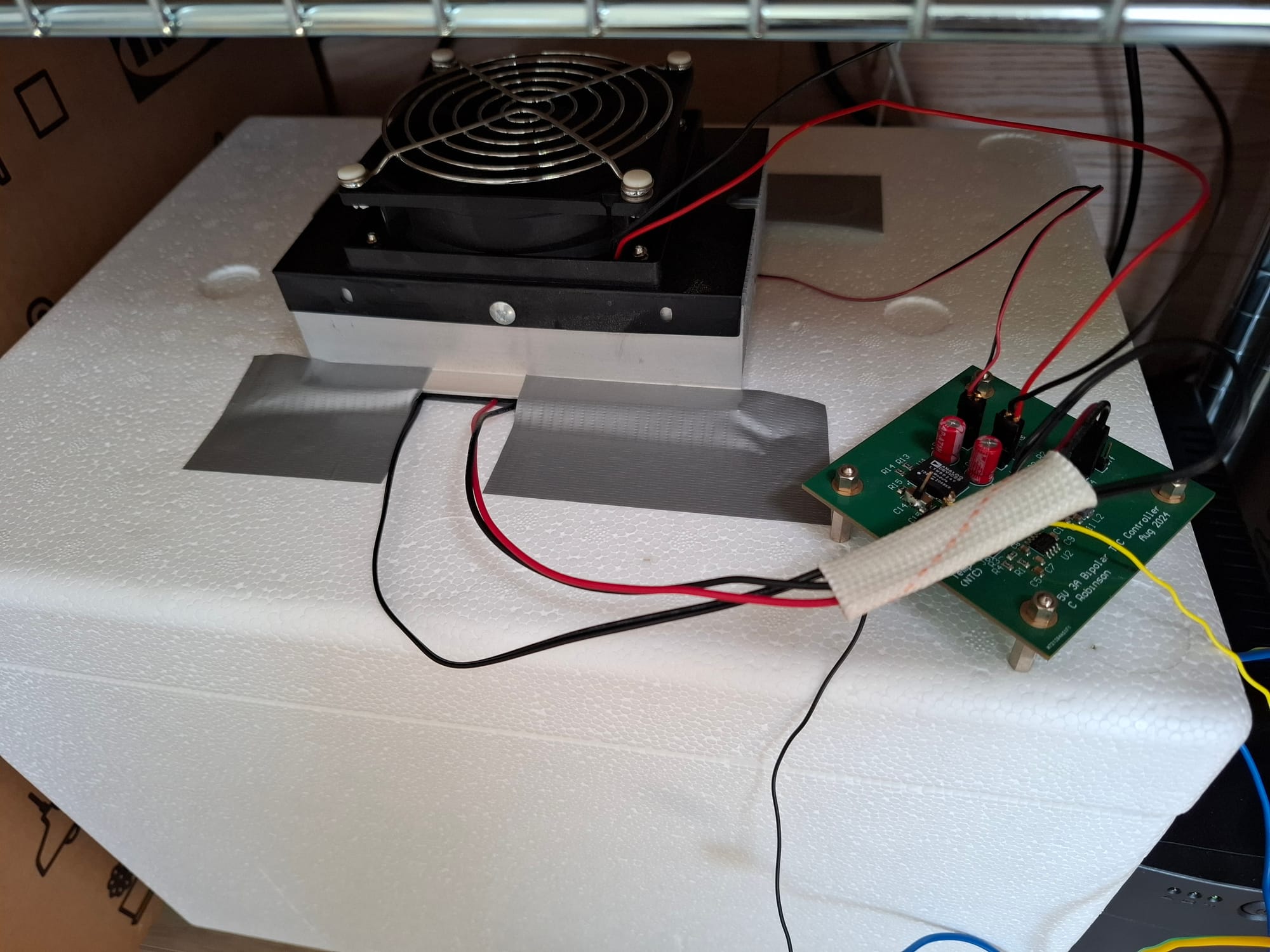
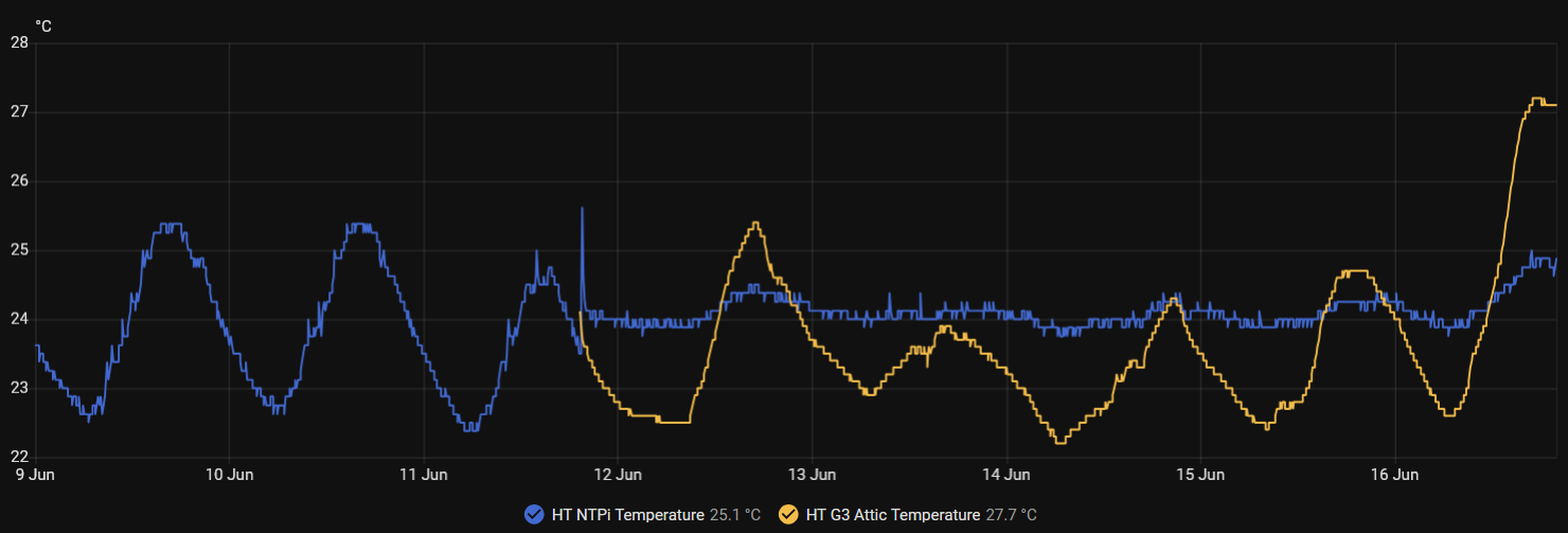
This temperature stabilised enclosure has had a tremendous impact on the temperature stability of the NTP Server's environment, shown below. It's not perfect, but it's enough to allow NTP Heat to keep the server temperature constant and not become unregulated in hot weather.
If we look at the same server metrics as at the start of the test, we get the following:
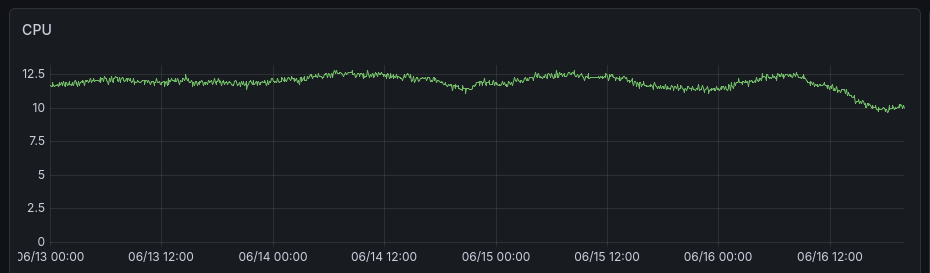
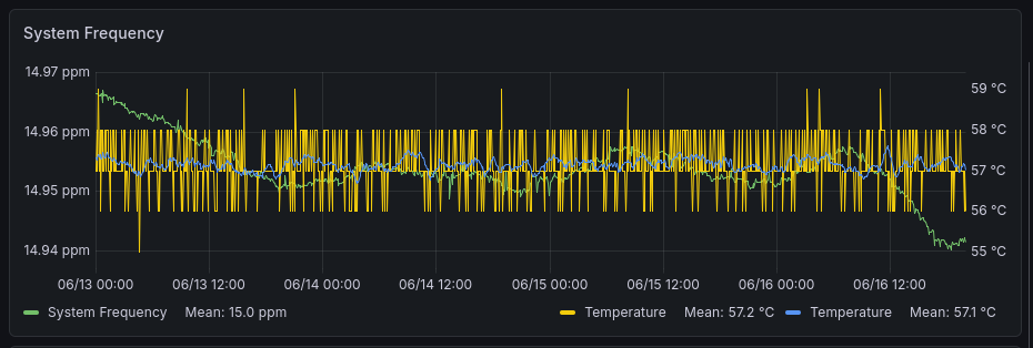
Clearly the CPU load from NTP Heat is much more constant, and the system temperature is looking stable. This in turn is stabilising the system frequency well.
Turning to the RMS Offset (including averaged over 1h and 24h), again there's a clear improvement. The system isn't much different than before during cooler weather, but it no longer becomes unstable in hotter weather.
To conclude, has this made an improvement? Yes, definitely. But not all installations may face this issue. My server is placed in an attic with a south facing roof and no air conditioning. Your own installation may be very different.
I'm hoping that at this point temperature stability is about as good as we're going to get and other factors can be explored.
GNSS - Disabling SBAS
Section 19.2 of the u-blox M8 Receiver description states that "for best time pulse performance it is recommended to disable the SBAS subsystem."
SBAS (Satellite-Based Augmentation System) is a form of GNSS Augmentation. It involves the distribution of correction information from navigation satellites to inform the receiver of the expected errors (such as clock drift and atmospheric effects) in its received signals from specific satellites.
Let's check out the currently enabled GNSS Constellations
ubxtool -p CFG-GNSS ::/dev/ttyAMA0The output below shows that GPS, SBAS, QZSS, and GLONASS are enabled.
UBX-CFG-GNSS:
 msgVer 0  numTrkChHw 32 numTrkChUse 32 numConfigBlocks 7
  gnssId 0 TrkCh  8 maxTrCh 16 reserved 0 Flags x01010001
   GPS L1C/A enabled
  gnssId 1 TrkCh  1 maxTrCh  3 reserved 0 Flags x01010001
   SBAS L1C/A enabled
  gnssId 2 TrkCh  4 maxTrCh  8 reserved 0 Flags x01010000
   Galileo E1
  gnssId 3 TrkCh  8 maxTrCh 16 reserved 0 Flags x01010000
   BeiDou B1I
  gnssId 4 TrkCh  0 maxTrCh  8 reserved 0 Flags x03010000
   IMES L1
  gnssId 5 TrkCh  0 maxTrCh  3 reserved 0 Flags x05010001
   QZSS L1C/A enabled
  gnssId 6 TrkCh  8 maxTrCh 14 reserved 0 Flags x01010001
   GLONASS L1 enabled
Now we disable SBAS
ubxtool -d SBAS ::/dev/ttyAMA0
An ACK comes back.
UBX-ACK-ACK:
  ACK to Class x06 (CFG) ID x3e (GNSS)
And a quick check to make sure that the setting worked.
ubxtool -p CFG-GNSS ::/dev/ttyAMA0The result is as follows:
UBX-CFG-GNSS:
 msgVer 0  numTrkChHw 32 numTrkChUse 32 numConfigBlocks 7
  gnssId 0 TrkCh  8 maxTrCh 16 reserved 0 Flags x01010001
   GPS L1C/A enabled
  gnssId 1 TrkCh  1 maxTrCh  3 reserved 0 Flags x01010001
   SBAS L1C/A
  gnssId 2 TrkCh  4 maxTrCh  8 reserved 0 Flags x01010000
   Galileo E1
  gnssId 3 TrkCh  8 maxTrCh 16 reserved 0 Flags x01010000
   BeiDou B1I
  gnssId 4 TrkCh  0 maxTrCh  8 reserved 0 Flags x03010000
   IMES L1
  gnssId 5 TrkCh  0 maxTrCh  3 reserved 0 Flags x05010001
   QZSS L1C/A enabled
  gnssId 6 TrkCh  8 maxTrCh 14 reserved 0 Flags x01010001
   GLONASS L1 enabled
Note save & coldboot via
ubxtool -p SAVE ::/dev/ttyAMA0
ubxtool -p COLDBOOT ::/dev/ttyAMA0
Below, we compare two 24h periods, one with SBAS disabled and one with SBAS enabled. The first image in each pair shows the location stability (difference from a defined point), and the second shows the RMS Offset and Root Dispersion.
Disabled:
Enabled:
To conclude, there appears to be no impact on timekeeping from using (or not using) SBAS. At least not enough to be noticeable.
I've chosen to keep it enabled, since it tightens up the location information a bit.
GNSS - Selecting GNSS constellations
The Galileo GNSS constellation provides very good timing performance due to the use of passive hydrogen masers on board the spacecraft.
Zhu et al found that "time transfer accuracy of BDS, GPS, GLONASS, and Galileo was 13.8 ns, 4.5 ns, 16.8 ns, and 4.2 ns, respectively" in the 2022 paper "GNSS Timing Performance Assessment and Results Analysis" Sensors 22, no. 7: 2486. https://doi.org/10.3390/s22072486
Our u-blox receiver doesn't enable Galileo by default, so let's enable it
ubxtool -e GALILEO ::/dev/ttyAMA0
An ACK comes back.
UBX-ACK-ACK:
  ACK to Class x06 (CFG) ID x3e (GNSS)
And a quick check to make sure that the setting worked.
ubxtool -p CFG-GNSS ::/dev/ttyAMA0Galileo is enabled!
UBX-CFG-GNSS:
 msgVer 0  numTrkChHw 32 numTrkChUse 32 numConfigBlocks 7
  gnssId 0 TrkCh  8 maxTrCh 16 reserved 0 Flags x01010001
   GPS L1C/A enabled
  gnssId 1 TrkCh  1 maxTrCh  3 reserved 0 Flags x01010001
   SBAS L1C/A
  gnssId 2 TrkCh  4 maxTrCh  8 reserved 0 Flags x01010001
   Galileo E1 enabled
  gnssId 3 TrkCh  8 maxTrCh 16 reserved 0 Flags x01010000
   BeiDou B1I
  gnssId 4 TrkCh  0 maxTrCh  8 reserved 0 Flags x03010000
   IMES L1
  gnssId 5 TrkCh  0 maxTrCh  3 reserved 0 Flags x05010001
   QZSS L1C/A enabled
  gnssId 6 TrkCh  8 maxTrCh 14 reserved 0 Flags x01010001
   GLONASS L1 enabled
Note save & coldboot via
ubxtool -p SAVE ::/dev/ttyAMA0
ubxtool -p COLDBOOT ::/dev/ttyAMA0
Now we can wait and see if there's an impact on timekeeping.
- GPS & GLONASS
- GPS
- GLONASS
- Galileo
- Galileo & GPS
- Galileo, GPS, GLONASS
GNSS - Setting the PPS frequency
Test planned.
Chrony - Setting the GNSS Offset
Test planned.
Chrony - Changing to SOCK interface
Test planned.
Chrony - Making Chrony stay in memory
Test planned.
Chrony - Reducing 'niceness'
Test planned.
Chrony - Using rtcsync
Test planned.
Chrony - Adding Rate Limiting
Test planned.
Also explore the impact of heavy load